这里针对 HMC5883L 磁力计 的校准,做一个简单讲解。

先看看这篇文章:http://blog.sina.com.cn/s/blog_8240cbef0101i7gn.html
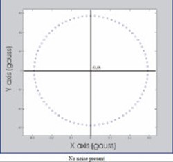
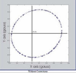
如果磁力计在含有附加的局部磁场的环境中进行操作,磁力计的输出做附加的修正将是必要的。 在没有任何本地磁场的影响下,下图1可以通过旋转设备360°产生的平面 ,图2为引入本地磁场。
方法一.修正的输出可以根据下面的方法来计算:
1)在磁场干扰的条件下进行,数据收集设备被旋转360°。
2)数据进行分析,以产生偏差的偏移和灵敏度的比例因子,以补偿所述干扰。
例子:
从数据中发现的X和Y磁强计的最大输出:
Xmin = -0.284gauss Xmax = +0.402gauss
Ymin = -0.322gauss Ymax = +0.246gauss
从中可以看出X轴的数据,X具有更大的反应,我们设置其比例系数为1
Xs = 1
再计算其他比例系数:
(Xmax – Xmin)
Ys = ————————
(Ymax – Ymin)
对于偏置补偿:
Xb = Xs[1/2(Xmax – Xmin) – Xmax ]
Yb = Ys[1/2(Ymax – Ymin) – Ymax ]
正确的输出:
Xout = Xin*Xs + Xb
Yout = Yin*Ys + Yb
方法二.
1)水平匀速旋转,收集XY轴数据
2)转动器材90度(Z轴)匀速转动以收集Z轴数据
Xoffset = (Xmax + Xmin)/2
Yoffset = (Ymax + Ymin)/2
Zoffset = (Zmax + Zmin)/2
将磁力计读到的裸值减去offset,得到用做角度计算的Heading值
XH = X – Xoffset
YH = Y – Yoffset
ZH = Z – Zoffset
水平测试,得到的方位角 = arctanYH/XH
非水平测试,需要使用加速计进行倾角补偿,先计算出翻滚角Roll和俯仰角Pitch,然后计算Heading值:
XH = x*cos(P)+Y*sin(R)*sin(P)-Z*cos(R)*sin(p)
YH = Y*cos(R)+Z*sin(R)

关于为什么设置偏置,请参考以下文章:
ST集成传感器方案实现电子罗盘功能:http://www.dzsc.com/data/html/2010-11-29/87454.html
HMC5883L常见问题解答:http://blog.sina.com.cn/s/blog_402c071e0102v8gj.html
这里我采用了上方的简单方法,来计算一个 offsetX, offsetY, offsetZ,然后减去这个偏移量,得到了正确的结果。下方是代码。下方我做了一个处理(诸如:mag.x*0.2 + magRange[0]*0.8)。是因为偶尔mag.x mag.y mag.z 会出现一个异常的值,使得计算的offsetX offsetY offsetZ不准,所以加了这个滤波处理。
static float magRange[6] = {1.0,-1.0,1.0,-1.0,1.0,-1.0};// magRange[0] 对应X最小,magRange[1] 对应X最大
// Magnetometer not yet used more then for logging.
// 磁力计尚未使用到,仅仅只是 log 记录下来。
imu9Read(&gyro, &acc, &mag);
if(magRange[0] > mag.x) magRange[0] = mag.x*0.2 + magRange[0]*0.8; // x min
if(magRange[1] < mag.x) magRange[1] = mag.x*0.2 + magRange[1]*0.8; // x max
if(magRange[2] > mag.y) magRange[2] = mag.y*0.2 + magRange[2]*0.8;
if(magRange[3] < mag.y) magRange[3] = mag.y*0.2 + magRange[3]*0.8;
if(magRange[4] > mag.z) magRange[4] = mag.z*0.2 + magRange[4]*0.8; // z min
if(magRange[5] < mag.z) magRange[5] = mag.z*0.2 + magRange[5]*0.8; // z max
magOffset[0] = (magRange[0]+magRange[1])/2.0;
magOffset[1] = (magRange[2]+magRange[3])/2.0;
magOffset[2] = (magRange[4]+magRange[5])/2.0;
mag.x -= magOffset[0];
mag.y -= magOffset[1];
mag.z -= magOffset[2];
自我检测也比较重要。通过HMC5883l芯片提供的自我检测功能,进行自我检测,然后找到一个比例因子。将传感器的检测值乘以这个比例因子,就可以修正磁场。我在代码中没有使用。相关的详细资料请看如下英文。
相关源代码,可以参考 Crazyflie firmware中的 bool hmc5883lSelfTest() 函数。
自我检测
SELF TEST OPERATION
To check the HMC5883L for proper operation, a self test feature in incorporated in which the sensor offset straps are excited to create a nominal field strength (bias field) to be measured. To implement self test, the least significant bits (MS1 and MS0) of configuration register A are changed from 00 to 01 (positive bias) or 10 (negetive bias), e.g. 0x11 or 0x12.
Then, by placing the mode register into single-measurement mode (0x01), two data acquisition cycles will be made on each magnetic vector. The first acquisition will be a set pulse followed shortly by measurement data of the external field. The second acquisition will have the offset strap excited (about 10 mA) in the positive bias mode for X, Y, and Z axes to create about a ±1.1 gauss self test field plus the external field. The first acquisition values will be subtracted from the second acquisition, and the net measurement will be placed into the data output registers.
Since self test adds ~1.1 Gauss additional field to the existing field strength, using a reduced gain setting prevents sensor from being saturated and data registers overflowed. For example, if the configuration register B is set to 0x60 (Gain=3), values around +766 LSB (1.16 Ga * 660 LSB/Ga) will be placed in the X and Y data output registers and around +713 (1.08 Ga * 660 LSB/Ga) will be placed in Z data output register. To leave the self test mode, change MS1 and MS0 bit of the configuration register A back to 00 (Normal Measurement Mode), e.g. 0x10.
比例因子校准
SCALE FACTOR CALIBRATION
Using the self test method described above, the user can scale sensors’ sensitivity to match each other. Since placing device in positive bias mode (or alternatively negative bias mode) applies a known artificial field on all three axes, the resulting ADC measurements in data output registers can be used to scale the sensors. For example, if the expected self test value for X-axis is 766 and the actual value is 750 then a scale factor of (766/750) should be multiplied to all future readings of X-axis. Doing so for all three axes will ensure their sensitivity are well matched.
The built-in self test can also be used to periodically compensate the scaling errors due to temperature variations. A compensation factor can be found by comparing the self test outputs with the ones obtained at a known temperature. For example, if the self test output is 750 at room temperature and 700 at the current temperature then a compensation factor of (750/700) should be applied to all current magnetic readings. A temperature sensor is not required using this method.

Crazyflie firmware中的 bool hmc5883lSelfTest() 函数代码如下,仅供参考:(函数中的各种定义这里未给出)
bool hmc5883lSelfTest()
{
bool testStatus = TRUE;
int16_t mxp, myp, mzp; // positive magnetometer measurements
int16_t mxn, myn, mzn; // negative magnetometer measurements
struct
{
uint8_t configA;
uint8_t configB;
uint8_t mode;
} regSave;
// Save register values
if (i2cdevRead(I2Cx, devAddr, HMC5883L_RA_CONFIG_A, sizeof(regSave), (uint8_t *)®Save) == FALSE)
{
// TODO: error handling
return FALSE;
}
// Set gain (sensitivity)
hmc5883lSetGain(HMC5883L_ST_GAIN);
// Write CONFIG_A register and do positive test
i2cdevWriteByte(I2Cx, devAddr, HMC5883L_RA_CONFIG_A,
(HMC5883L_AVERAGING_1 << (HMC5883L_CRA_AVERAGE_BIT – HMC5883L_CRA_AVERAGE_LENGTH + 1)) |
(HMC5883L_RATE_15 << (HMC5883L_CRA_RATE_BIT – HMC5883L_CRA_RATE_LENGTH + 1)) |
(HMC5883L_BIAS_POSITIVE << (HMC5883L_CRA_BIAS_BIT – HMC5883L_CRA_BIAS_LENGTH + 1)));
hmc5883lSetMode(HMC5883L_MODE_SINGLE);
vTaskDelay(M2T(HMC5883L_ST_DELAY_MS));
hmc5883lGetHeading(&mxp, &myp, &mzp);
// Write CONFIG_A register and do negative test
i2cdevWriteByte(I2Cx, devAddr, HMC5883L_RA_CONFIG_A,
(HMC5883L_AVERAGING_1 << (HMC5883L_CRA_AVERAGE_BIT – HMC5883L_CRA_AVERAGE_LENGTH + 1)) |
(HMC5883L_RATE_15 << (HMC5883L_CRA_RATE_BIT – HMC5883L_CRA_RATE_LENGTH + 1)) |
(HMC5883L_BIAS_NEGATIVE << (HMC5883L_CRA_BIAS_BIT – HMC5883L_CRA_BIAS_LENGTH + 1)));
hmc5883lSetMode(HMC5883L_MODE_SINGLE);
vTaskDelay(M2T(HMC5883L_ST_DELAY_MS));
hmc5883lGetHeading(&mxn, &myn, &mzn);
if (hmc5883lEvaluateSelfTest(HMC5883L_ST_X_MIN, HMC5883L_ST_X_MAX, mxp, “pos X”) &&
hmc5883lEvaluateSelfTest(HMC5883L_ST_Y_MIN, HMC5883L_ST_Y_MAX, myp, “pos Y”) &&
hmc5883lEvaluateSelfTest(HMC5883L_ST_Z_MIN, HMC5883L_ST_Z_MAX, mzp, “pos Z”) &&
hmc5883lEvaluateSelfTest(-HMC5883L_ST_X_MAX, -HMC5883L_ST_X_MIN, mxn, “neg X”) &&
hmc5883lEvaluateSelfTest(-HMC5883L_ST_Y_MAX, -HMC5883L_ST_Y_MIN, myn, “neg Y”) &&
hmc5883lEvaluateSelfTest(-HMC5883L_ST_Z_MAX, -HMC5883L_ST_Z_MIN, mzn, “neg Z”))
{
DEBUG_PRINT(“Self test [OK].\n”);
}
else
{
testStatus = FALSE;
}
// Restore registers
if (i2cdevWrite(I2Cx, devAddr, HMC5883L_RA_CONFIG_A, sizeof(regSave), (uint8_t *)®Save) == FALSE)
{
// TODO: error handling
return FALSE;
}
return testStatus;
}
另外这里提供了一个方法,日后若有研究,我将给出详细说明,这里提供链接供参考:
http://bbs.kechuang.org/read/67382

研究了一晚上稍微有点成果分享下
HMC5883L使用i2c接口,接线很容易
以Arduino Uno为例:
SDA to A4
SCL to A5
Vcc to 3.3V
GND to GND
基本原理很简单:
方向角其实就是X轴和Y轴读数的反正切
而校准其实就是要排除环境中的磁场对地磁场的干扰
另外别忘了当地的磁偏角
如下代码没有使用专门的传感器库
上电后先进行20秒校准,请把传感器任意乱转,各个方向都要转到
然后就会显示校准值,然后持续显示初始值和方向角
不知道怎么在ide里面用中文写注释,所以就保留英文了
个人测试下来和手机上的指南针相差不超过5度,更精细的校准待研究
刚刚接触Arduino,望高手指教
ARDUINO 代码复制打印
-
#include <Wire.h> //I2C Arduino Library
-
-
#define address 0x1E //001 1110b(0x3C>>1), I2C 7bit address of HMC5883
-
#define MagnetcDeclination 4.43
//Shanghai
-
#define CalThreshold 0
-
-
int offsetX,offsetY,offsetZ;
-
-
void
setup()
-
{
-
//Initialize Serial and I2C communications
-
Serial.begin(9600);
-
Wire.begin();
-
-
//Put the HMC5883 IC into the correct operating mode
-
Wire.beginTransmission(address); //open communication with HMC5883r
-
Wire.write(0x00); //select configuration register A
-
Wire.write(0x70); //0111 0000b configuration
-
Wire.endTransmission();
-
-
Wire.beginTransmission(address);
-
Wire.write(0x02); //select mode register
-
Wire.write(0x00); //set continuous measurement mode:0x00,single-measurement mode:0x01
-
Wire.endTransmission();
-
-
calibrateMag();
-
}
-
void
loop()
-
{
-
int x,y,z; //triple axis data
-
getRawData(&x,&y,&z);
-
-
//Print out values of each axis
-
Serial.print(“x: “);
-
Serial.print(x);
-
Serial.print(” y: “);
-
Serial.print(y);
-
Serial.print(” z: “);
-
Serial.print(z);
-
Serial.print(” angle(x,y): “);
-
Serial.println(calculateHeading(&x,&y,&z));
-
-
delay(250);
-
}
-
-
void getRawData(int* x ,int* y,int* z)
-
{
-
//Tell the HMC5883L where to begin reading data
-
Wire.beginTransmission(address);
-
Wire.write(0x03); //select register 3, X MSB register
-
Wire.endTransmission();
-
//Read data from each axis, 2 registers per axis
-
Wire.requestFrom(address, 6);
-
if(6<=Wire.available()){
-
*x = Wire.read()<<8; //X msb
-
*x |= Wire.read(); //X lsb
-
*z = Wire.read()<<8; //Z msb
-
*z |= Wire.read(); //Z lsb
-
*y = Wire.read()<<8; //Y msb
-
*y |= Wire.read(); //Y lsb
-
}
-
}
-
-
int calculateHeading(int* x ,int* y,int* z)
-
{
-
float headingRadians = atan2((double)((*y)-offsetY),(double)((*x)-offsetX));
-
// Correct for when signs are reversed.
-
if(headingRadians < 0)
-
headingRadians += 2*PI;
-
-
int headingDegrees = headingRadians * 180/M_PI;
-
headingDegrees += MagnetcDeclination; //the magnetc-declination angle
-
-
// Check for wrap due to addition of declination.
-
if(headingDegrees > 360)
-
headingDegrees -= 360;
-
-
return headingDegrees;
-
}
-
-
void calibrateMag()
-
{
-
int x,y,z; //triple axis data
-
int xMax, xMin, yMax, yMin, zMax, zMin;
-
//initialize the variables
-
getRawData(&x,&y,&z);
-
xMax=xMin=x;
-
yMax=yMin=y;
-
zMax=zMin=z;
-
offsetX = offsetY = offsetZ = 0;
-
-
Serial.println(“Starting Calibration……”);
-
Serial.println(“Please turn your device around in 20 seconds”);
-
-
for(int i=0;i<200;i++)
-
{
-
getRawData(&x,&y,&z);
-
//get Max and Min
-
// this routine will capture the max and min values of the mag X, Y, and Z data while the
-
// compass is being rotated 360 degrees through the level plane and the upright plane.
-
// i.e. horizontal and vertical circles.
-
// This function should be invoked while making continuous measurements on the magnetometers
-
if
(x > xMax)
-
xMax = x;
-
if
(x < xMin )
-
xMin = x;
-
if(y > yMax )
-
yMax = y;
-
if(y < yMin )
-
yMin = y;
-
if(z > zMax )
-
zMax = z;
-
if(z < zMin )
-
zMin = z;
-
-
delay(100);
-
-
if(i%10 == 0)
-
{
-
Serial.print(xMax);
-
Serial.print(” “);
-
Serial.println(xMin);
-
}
-
}
-
//compute offsets
-
if(abs(xMax – xMin) > CalThreshold )
-
offsetX = (xMax + xMin)/2;
-
if(abs(yMax – yMin) > CalThreshold )
-
offsetY = (yMax + yMin)/2;
-
if(abs(zMax – zMin) > CalThreshold )
-
offsetZ = (zMax +zMin)/2;
-
-
Serial.print(“offsetX:”);
-
Serial.print(“”);
-
Serial.print(offsetX);
-
Serial.print(” offsetY:”);
-
Serial.print(“”);
-
Serial.print(offsetY);
-
Serial.print(” offsetZ:”);
-
Serial.print(“”);
-
Serial.println(offsetZ);
-
-
delay(5000);
-
}
把冗长的数据手册读完了,有人想看的话,可以把自测试模式,空闲模式等的使用方法也写一下
参考资料:
https://www.sparkfun.com/tutorials/301 HMC5883L SW_Routine_Calibration.pdf (91.42 KB, 下载次数: 196)
转载请注明:徐自远的乱七八糟小站 » 【转贴】HMC5883L 磁力计校准